Reference design · NPL-GOV-002-R1

Government building · two physically separate networks

An illustrative public-service network and restricted office network with independent switches, uplinks, fiber cables and management paths.

H3C equipment · NexPro-Link design, selection & project supply

Government networking application environment
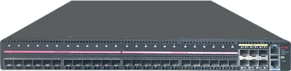
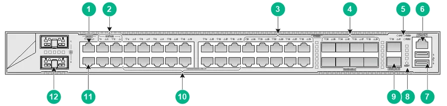
H3C FS5500V2-24UXS6Y-EI — official product photograph
H3C FS5500V2-24UXS6Y-EI · Official product source ↗

Point-to-point optical Ethernet

A defined starting point for technical review.

This is an illustrative reference design, not a completed installation or a final site quotation. Quantities and capacities follow the assumptions below.

Scale & assumptions

  • The project owner requires two separate data networks. Each network has its own gateway, core and two access switches; no shared core, trunk or PON system.
  • Public network: up to 32 desk/phone ports, four APs and eight cameras. Restricted network: up to 40 wired workstations, no WLAN in this reference.
  • Separate labeled fiber cables, patch panels and management/service interfaces are assumed. Approved pathways, room access and separation rules must be provided by the authority.
  • Reference diagrams demonstrate physical data separation only. They are not a certification of compliance with a national government security standard.

Why this architecture

Conventional point-to-point Ethernet makes the independent physical paths clear. The same H3C model may be used in both networks, but each is a separate physical device with its own configuration and administration.

When to choose another approach

A shared core with VLANs/VRFs is a different logical-segmentation option and is not acceptable when the project requires the physical separation shown here. PON could be assessed only as two independently provisioned physical infrastructures under the authority's requirements.

Compare the three architecture families →

Public service network A

Reception terminals, public/staff WLAN and public-area surveillance.

Service boundary: Own ISP/gateway, core, switches, fiber and management; guest policy still required.

Restricted network B

40 wired office workstation connections and internal services.

Service boundary: Authority-approved private handoff only; no implied Internet connection or route to network A.

Management / service rooms

Independent administration and application/recording services.

Service boundary: No dual-homed host bridging A and B. Transfers, if permitted, require an independently approved mechanism.

New construction

Specify independent cable identifiers, patching, racks/compartments and administration paths from the drawings. Agree the authority's physical separation, secure-room and acceptance requirements before tendering equipment.

Upgrade / retrofit

Trace every existing uplink, wireless bridge, server NIC and management path. Remove unapproved shared paths only within an authorized migration plan; prove isolation by inspection and controlled connectivity tests before acceptance.

Government building · two physically separate networks

Physical connections
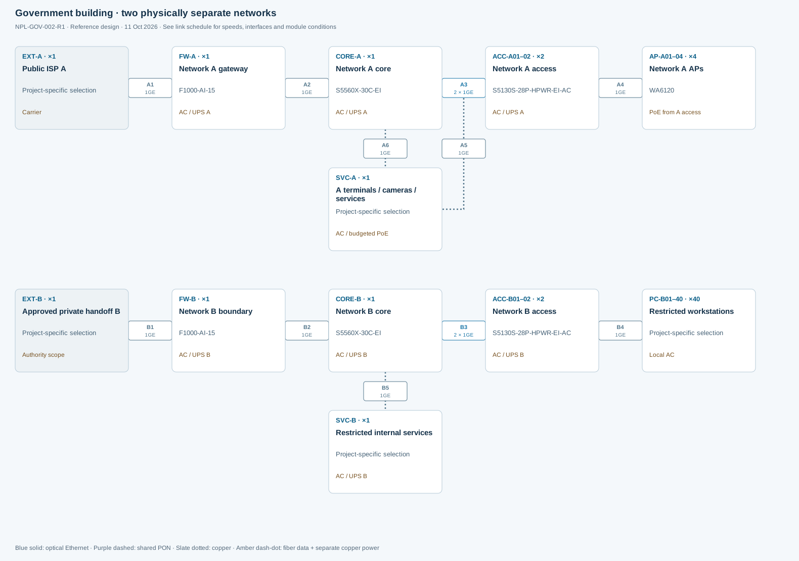
Government building · two physically separate networksReference design. Device IDs match the BOM. Connection IDs match the HTML link schedule. Use separately scheduled A and B circuits/UPS outlets as specified by the authority and local electrical design. Physical data isolation is evaluated through equipment and data paths, not inferred from a UPS label. No shared PoE switch serves both networks.Government building · two physically separate networksNPL-GOV-002-R1 · Reference design · 11 Oct 2026 · See link schedule for speeds, interfaces and module conditionsA11GEA21GEA32 × 1GEA41GEA51GEA61GEB11GEB21GEB32 × 1GEB41GEB51GEEXT-A · ×1Public ISP AProject-specific selectionCarrierFW-A · ×1Network A gatewayF1000-AI-15AC / UPS ACORE-A · ×1Network A coreS5560X-30C-EIAC / UPS AACC-A01–02 · ×2Network A accessS5130S-28P-HPWR-EI-ACAC / UPS AAP-A01–04 · ×4Network A APsWA6120PoE from A accessEXT-B · ×1Approved private handoff BProject-specific selectionAuthority scopeFW-B · ×1Network B boundaryF1000-AI-15AC / UPS BCORE-B · ×1Network B coreS5560X-30C-EIAC / UPS BACC-B01–02 · ×2Network B accessS5130S-28P-HPWR-EI-ACAC / UPS BPC-B01–40 · ×40Restricted workstationsProject-specific selectionLocal ACSVC-A · ×1A terminals / cameras /servicesProject-specific selectionAC / budgeted PoESVC-B · ×1Restricted internal servicesProject-specific selectionAC / UPS BBlue solid: optical Ethernet · Purple dashed: shared PON · Slate dotted: copper · Amber dash-dot: fiber data + separate copper power
Reference design · NPL-GOV-002-R1 · Device IDs match the BOM. Link IDs match the connection schedule below. Scroll horizontally or open the SVG for a larger view.

Logical services & boundaries

Network A and B have no drawn interconnection. VLANs may segment services inside either network, but do not create the physical separation. Separate administration, logging and authentication must follow the authority's requirements.

Electrical power path

Use separately scheduled A and B circuits/UPS outlets as specified by the authority and local electrical design. Physical data isolation is evaluated through equipment and data paths, not inferred from a UPS label. No shared PoE switch serves both networks.

Link schedule — interfaces, bandwidth and components
Link / endpointsSpeed / sharingPhysical path & interfacesModules / configuration conditions
A1
EXT-A → FW-A
1GE
Dedicated link / channels
Public ISP A handoff.Carrier interface confirmation.
A2
FW-A → CORE-A
1GE
Dedicated link / channels
A-only gateway to core.Dedicated A patch cable.
A3
CORE-A → ACC-A01–02
2 × 1GE
Dedicated link / channels
Two dedicated A fibers, using core GE combo optical interfaces.2 GE optical pairs; dedicated A ODF and separately labeled cable runs.
A4
ACC-A01–02 → AP-A01–04
1GE
Dedicated link / channels
2 APs per A access switch.4 Cat6 AP channels; only A service mapping.
A5
ACC-A01–02 → SVC-A
1GE
Dedicated link / channels
16 desk/phone + 4 camera ports per A access switch.A-only endpoint patches; service hosts use the separate A6 connection.
A6
CORE-A → SVC-A
1GE
Dedicated link / channels
Separate core GE connections for A-only application and management hosts within the service package.Application host NICs and counts remain to be specified. These are separate devices from the A5 endpoints, with no interface to B.
B1
EXT-B → FW-B
1GE
Dedicated link / channels
Authority-approved private B boundary.Interface and appliance suitability subject to authority approval.
B2
FW-B → CORE-B
1GE
Dedicated link / channels
B-only boundary to core; no connection to A.Dedicated B patch cable.
B3
CORE-B → ACC-B01–02
2 × 1GE
Dedicated link / channels
Two independent B fiber cable routes/ODF, not A trunk VLANs.2 GE optical pairs, B patch panels and cable schedule.
B4
ACC-B01–02 → PC-B01–40
1GE
Dedicated link / channels
20 wired workstation channels per B switch.40 dedicated B copper channels.
B5
CORE-B → SVC-B
1GE
Dedicated link / channels
Restricted services connect only to B.B-only server interfaces and management connections; no bridging host.

Declared inputs · reviewable calculations

Capacity and power, with their limits visible.

Planning allocations are assumptions, not measurements of unselected endpoints. Reconcile them with the final device classes, configuration and site tests.

Public ports

2 × (16 desks/phones + 2 APs + 4 cameras) =44 assigned copper ports; 48 available.

4 spare ports. Separate core service ports must also be scheduled.

Restricted ports

2 × 20 =40 workstation connections from 48 access ports.

8 spare access ports. All B uplinks, patches and management interfaces remain physically separate.

Public PoE example

Per A switch: 2 APs ×16W + 4 cameras ×15W + up to 8 phones ×8W =156W; 20% reserve =187.2W.

Within the selected 370W model budget; reconcile exact endpoint classes before ordering.

Isolation acceptance

Separate 2 gateways + 2 cores + 4 access switches + independent cable/ODF schedules.

Inspect for shared uplinks, dual-homed servers, wireless bridges and management links. Compliance requires the authority's approved design and acceptance process.

NPL-GOV-002-R1 · preliminary purchasing basis

The same device IDs. A complete BOM scope.

Download BOM · CSV

Quantities below follow the stated reference assumptions. “To confirm” identifies configuration or survey work still needed before a firm equipment order. Optional resilience is separate from the baseline.

ID / roleModel / itemQty / scopePower / configuration / open items
FW-A
Network A gateway
F1000-AI-15
Official source ↗
1 units / sets
Required
AC / UPS A
Public policy boundary; enabled-service sizing required.
CORE-A
Network A core
S5560X-30C-EI
Official source ↗
1 units / sets
Required
AC / UPS A
Independent hardware and management.
ACC-A01–02
Network A access
S5130S-28P-HPWR-EI-AC
Official source ↗
2 units / sets
Required
AC / UPS A
Separate A fiber cables/patch panels. 22 of 24 copper ports assigned per switch.
AP-A01–04
Network A APs
WA6120
Official source ↗
4 units / sets
Required
PoE from A access
Only public/staff A network services; no restricted B SSID.
FW-B
Network B boundary
F1000-AI-15
Official source ↗
1 units / sets
Required
AC / UPS B
Subject to authority security platform and approval requirements.
CORE-B
Network B core
S5560X-30C-EI
Official source ↗
1 units / sets
Required
AC / UPS B
No A uplink or common management interface.
ACC-B01–02
Network B access
S5130S-28P-HPWR-EI-AC
Official source ↗
2 units / sets
Required
AC / UPS B
Dedicated B fiber cables/patch panels; 20 assigned + 4 spare ports per switch.
PC-B01–40
Restricted workstations
Project-specific selection40 units / sets
Required
Local AC
No shared NIC/bridge to A; endpoint security follows authority policy.
SVC-A
A terminals / cameras / services
Project-specific selection1 units / sets
Required
AC / budgeted PoE
32 desk/phone ports + 8 cameras; independent service hosts and management.
SVC-B
Restricted internal services
Project-specific selection1 units / sets
Required
AC / UPS B
Dedicated B hosts/storage/admin scope. Quantity is a service package pending application sizing.
A-PWR
Core/gateway power configuration, cords and fan sets
Core/gateway power configuration, cords and fan sets1 engineered set
Required
Per approved configuration
Select compatible supplies and airflow for the listed devices. Confirm mains, plugs, loading and service availability; no unlisted PSU is assumed included.
A-LIC
Management, security and WLAN licenses / support
Management, security and WLAN licenses / support1 scope
Required
Per approved configuration
Quote controller or cloud mode, AP capacity, security subscriptions, country codes and support term explicitly. Final SKUs remain subject to configuration review.
A-RACK
Racks, PDU, UPS, earthing and patch management
Racks, PDU, UPS, earthing and patch managementTo confirm surveyed scope
Required
Per approved configuration
Size actual equipment depth, ventilation, total input load, autonomy, outlets and grounding. UPS kVA and battery runtime are not inferred from floor count.
A-GE
GE optical pairs
GE optical pairs4 pairs
Required
Per approved configuration
Two A links and two B links, with independent fiber cables/patching.
A-ODF
Independent A / B fiber and patch schedules
Independent A / B fiber and patch schedules2 networks
Required
Per approved configuration
Document separate cables, labels, ODF, equipment ports and maintenance paths; authority determines required physical clearance.
A-SEC
Approved management / authentication / security scope
Approved management / authentication / security scope2 networks
Required
Per approved configuration
Independent service/admin domains and product eligibility review; hardware examples are not compliance certification.
A-REDUND
Redundancy within each independent network
Redundancy within each independent networkTo confirm option
Optional
Per approved configuration
Add approved backup devices and diverse paths inside A and inside B; never use a shared cross-network backup link.

Shared with the topology and BOM

Review the selected H3C candidates.

Compare specifications & configure quantities →
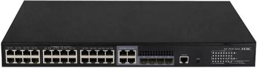
H3C S5130S-28P-HPWR-EI-AC — official product photograph

Copper PoE access

S5130S-28P-HPWR-EI-AC

Small or medium local PoE access with GE fiber uplinks.

370W total; official full-load examples: 24 af ports or 12 at ports.

Model, source & quote selection →
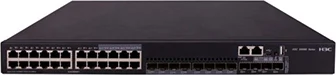
H3C S5560X-30C-EI — official product photograph

Compact campus core / aggregation

S5560X-30C-EI

Modest routed networks with a checked uplink and service port plan.

Published maximum dual AC consumption 91W for listed configuration; recalculate with expansion/optics.

Model, source & quote selection →
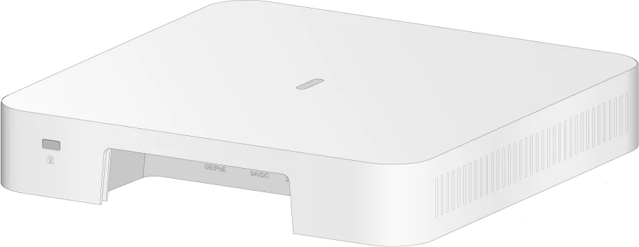
H3C WA6120 — official hardware drawing

Indoor Wi-Fi 6 AP

WA6120

Indoor access with a GE wired connection and low power demand.

Operating consumption ≤12.95W; reserve 15.4W at an af PSE before cable loss assumptions.

Model, source & quote selection →
H3C F1000-AI-15 — official hardware drawing

Enterprise security gateway

F1000-AI-15

A candidate WAN / policy boundary, sized after enabled-service throughput review.

Hardware guide lists 48W device power consumption.

Model, source & quote selection →

Next useful inputs

Turn this example into your project.

  • Authority's classification, approved products and physical isolation criteria
  • Independent A/B floor plans, cable routes and service/management endpoints
  • Security acceptance, logging, authentication and data transfer rules
  • Availability targets, power design and controlled maintenance process
Download the input checklist

NexPro-Link support scope

From selection to coordinated supply.

  • Independent equipment and cable schedules
  • Traffic-boundary and management-path review
  • Authority-ready open-item list and procurement alternatives
  • Separate A/B BOM, labeling and acceptance checklist

Detailed deliverables, design fees where applicable, site survey, installation and acceptance responsibilities are agreed for the project stage. Local statutory and specialist system approvals remain with the appointed teams.

Your next step

Start with the information you have.

Send a short requirement, drawings, an existing BOQ or the exact H3C models you need. We will identify the selection and supply scope.

The page, architecture and reference equipment are included automatically. Your selected quote-list quantities can be edited before sending.

Add project details, if known

One attachment up to 3 MB, or a shared-file link. Unknown engineering fields can be confirmed later.

Send a quick inquiry

A short message is enough to get started.

Contact and inquiry details
I’m interested in
Page details included with your inquiry

Request: Network design from drawings · Reference design: NPL-GOV-002-R1 · Architecture: Point-to-point optical Ethernet · Reference equipment (subject to review): FW-A: F1000-AI-15 ×1; CORE-A: S5560X-30C-EI ×1; ACC-A01–02: S5130S-28P-HPWR-EI-AC ×2; AP-A01–04: WA6120 ×4; FW-B: F1000-AI-15 ×1; CORE-B: S5560X-30C-EI ×1; ACC-B01–02: S5130S-28P-HPWR-EI-AC ×2

Add company details or a file (optional)

PDF, DWG, Excel, CSV, JPG, PNG or Word · up to 3 MB.

We use these details to respond to your inquiry. Privacy policy

Prefer a conversation? WhatsApp us or send an email.

Catalog Chat